Characteristics: The flanges of I-beams are sloped with rounded edges at the flange ends. When using bolting connections, specialized shims designed for sloped surfaces are required for assistance. This complicates the installation process.
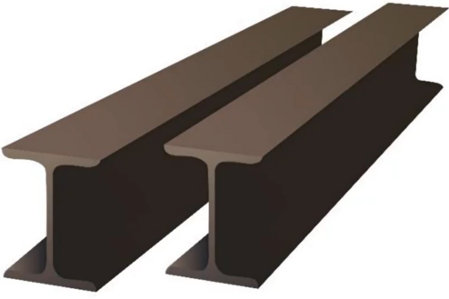
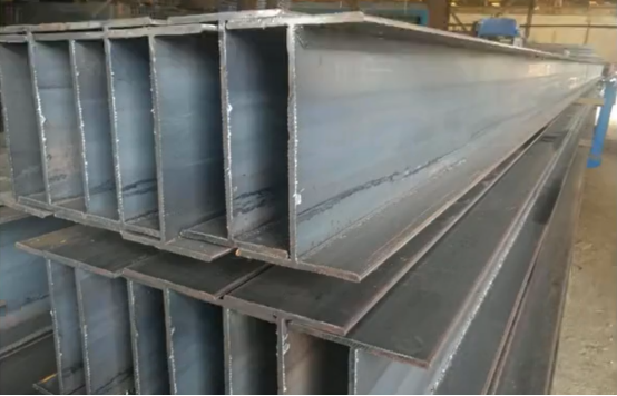
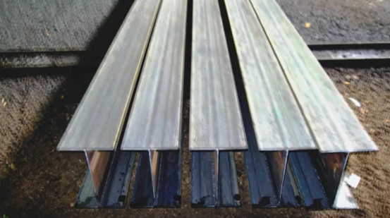
2) Welded H-section Steel
Characteristics: Fabricated from three steel plates in a controlled factory environment, resulting in a straightforward manufacturing process. The members inherently maintain rectilinear geometry. Unlike I-beams (which feature sloped flanges with rounded edges and complicate installation), H-section steel is consequently preferred over I-beams for modern structural applications. I-beams are rarely used in contemporary building construction.
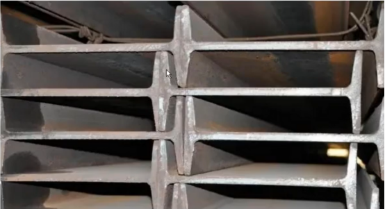
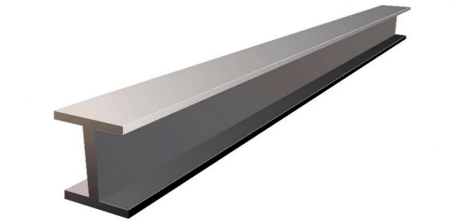
3) Hot-rolled H-section Steel
Characteristics: Features predetermined dimensional parameters as standardized by national specifications, prohibiting dimensional modifications. Key differentiation from welded H-section steel: Hot-rolled sections maintain fixed geometrical profiles, whereas welded H-sections are fabricated by joining three steel plates according to design drawings.
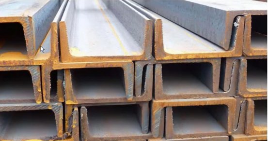
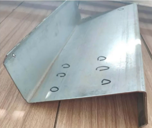
4)Channel section
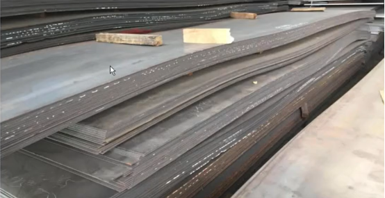
5)Steel plates
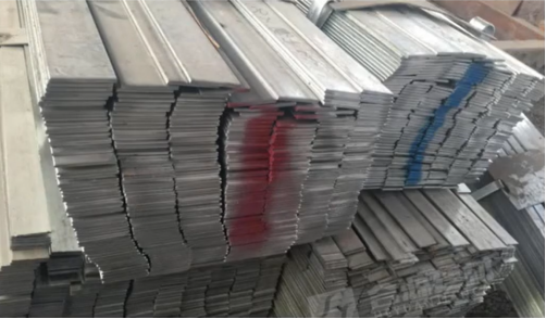
6)Flat steel bar
Flat bar, also known as flat steel bar, derives its name from its narrow width relative to plate steel, as illustrated below. Its length can be customized as required.
7)Square Bar
Note: Square bar must be solid, not hollow.
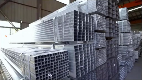
8)Square tube
Note: Square tube must be hollow, not solid.
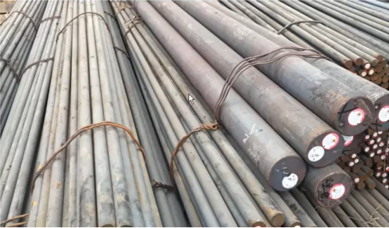
9)Round bar
Note: Round bar must be solid (not hollow) with smooth surface finish.
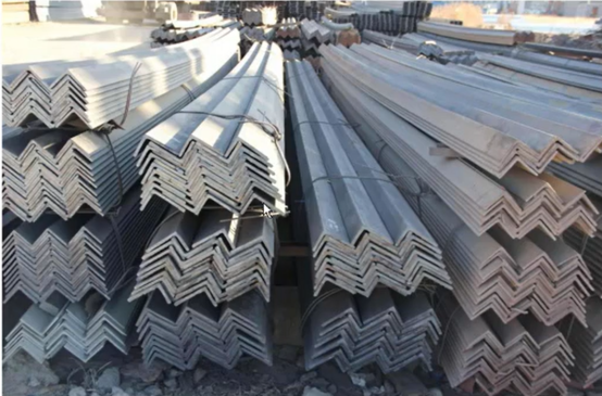
10)Angle Steel
Sections are represented by L-figures. Example: L80X60X6 indicates an unequal leg angle with leg widths of 80mm and 60mm, and leg thickness of 6mm; L100X6 indicates an equal leg angle with leg width of 100mm and leg thickness of 6mm; Thin-walled sections are marked with “B”, e.g. BL60x2 denotes a thin-walled equal leg angle with side length of 60mm and wall thickness of 2mm.
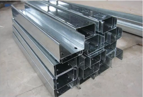
11)Lipped C-Section
“C” shape
12)Z-Section
A “Z” shape as shown in the diagram below.
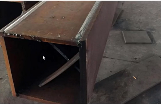
13)Box Section
Its appearance resembles a rectangular box.
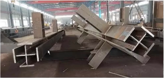
14)Cruciform Section
Structurally analogous to two H-sections joined perpendicularly to form a cross-shaped profile.
Powerful converging forces are driving substantial growth potential in the global prefabricated building and structural steel market, indicating strong future purchasing power for these solutions.
Key Growth factors including as following: Urbanization & Infrastructure Boom: Rapid city growth, especially in Asia-Pacific, coupled with massive government investments in bridges, transit networks, and smart cities, is fundamentally increasing demand.
Sustainability Imperative: Steel’s near-100% recyclability, lower production energy footprint compared to alternatives like concrete, and inherent ability to reduce construction waste align perfectly with stringent green building standards and global carbon reduction goals.
Technological Advancements: Innovations including high-strength steels, advanced corrosion protection, and cleaner production methods enhance performance, durability, and environmental credentials.
Regional Dynamics: Asia-Pacific Leads Global Demand: Why? Massive numbers of people are moving to cities (urbanization) very quickly, especially in China and India. This requires huge amounts of new housing, offices, factories, roads, bridges, and power systems.This huge building boom uses more prefabricated buildings and structural steel than anywhere else in the world.
North America & Europe Growth Drivers: Sustainability Mandates: Governments and building codes are pushing hard for “green” construction. Steel’s recyclability fits perfectly with these rules. Energy Efficiency Regulations: New buildings must use less energy. Steel structures can be designed to be very energy efficient.
Infrastructure Modernization: Old roads, bridges, and public buildings in these regions need replacing or upgrading. Steel is a key material for these projects.
Market Segmentation: Types:
Prefabricated Buildings: Whole buildings or major sections made in a factory and assembled on-site (e.g., modular homes, prefab offices). Structural Steel: Individual steel parts (like beams, columns, frames) used to build structures, whether prefabricated or built traditionally. Applications (Where it’s used): Residential: Houses, apartments. Commercial: Offices, stores, shopping malls, hotels. Industrial: Factories, warehouses, power plants. Infrastructure: Bridges, roads, railways, airports, dams. Key Point: Infrastructure projects (like bridges and highways) use a very large amount of structural steel, making this application sector extremely important.
Growth Outlook: Why Strong Growth is Expected: Three big forces are working together: Urbanization: More people moving to cities = need for much more building. Sustainability Demands: The world needs greener construction; steel’s recyclability helps meet this. Technological Progress: Better, stronger, and more eco-friendly ways to make and use steel are being developed. This powerful combination points to strong, steady, and long-lasting growth in the market for both prefabricated buildings and the structural steel parts used to build things. Demand is expected to keep rising significantly.
1. Fabrication of Template Rods and Templates Templates may be fabricated from sheet iron or plastic plates with a thickness of 0.50–0.75 mm. Accuracy requirements are specified in Table 6-2. Template rods are generally made from sheet iron or flat steel; wooden rods may be used for shorter lengths. Template rods and templates shall be marked with the work order number, drawing number, part number, quantity, edges to be machined, bevel locations, bend lines and bending directions, hole diameters, and rolling radii. Template rods and templates shall be properly stored and may only be discarded after project completion.
2. Marking Out Verify steel specifications, material grade, and batch number. Remove oil, soil, and contaminants from the steel plate surface. Marking out methods include: centralized marking, nesting, statistical calculation, and unified marking for remnant materials. If surface quality fails to meet requirements, steel shall be straightened. Straightening of steel and components shall be performed using plate levelers or section straightening machines. Thicker plates may also be straightened using presses or flame heating. Manual hammer straightening shall be gradually phased out. Cold straightening and cold bending shall not be performed on carbon structural steel when the ambient temperature is below -16°C, or on low-alloy structural steel below -12°C. After straightening, steel surfaces shall exhibit no obvious indentations or damage. Scratch depth shall not exceed 0.5 mm and shall not be greater than half the negative tolerance of the steel thickness.
3. Layout Layout is performed using fabrication drawings, template rods, templates, and steel tape measures. Some advanced steel fabrication plants now employ CNC automatic marking machines, which offer high efficiency, precision, and material savings. Two key principles for layout: ①Layout operations shall be conducted indoors, shielded from direct sunlight and external temperatures, preferably in spacious, well-lit areas. ②Layout accuracy is higher using scribers than ink markers or marking cords. Scriber tips may be ground sharp on grinding wheels, achieving a tip width of approximately 0.3 mm. Three layout methods exist: pre-layout, post-layout, and general pre-layout with subsequent end layout. When laying out cutting sections, account for shear allowance and machining allowance.
4. Cutting Steel cutting methods include high-temperature thermal processes (laser cutting, gas cutting, plasma cutting) and mechanical force methods (shearing, sawing, friction heat). Consider cutting capacity, accuracy, quality of the cut surface, and economics.
5. Edge Preparation and End Machining Primary methods: chipping, planing, milling, carbon arc gouging, gas cutting, and groove machining. Chipping: Includes manual and mechanical chipping. Vertical angular deviation after chipping shall not exceed L/3000 of the chord length and shall not exceed 2 mm. Planing: Uses planers. Includes straight edge planing and bevel edge planing. Typical machining allowance is 2–4 mm. Milling: Uses milling machines. Offers high efficiency and low energy consumption. Carbon Arc Gouging: Uses arc gouging torches. Features high efficiency, no noise, flexibility, and convenience. Groove Machining: Generally performed using thermal or mechanical methods. Manual gas cutting may be used exceptionally but requires post-processing (e.g., grinding). Dedicated groove machining equipment is now common, including specialized machines for H-beam and curved grooves, offering high efficiency and precision. Weld quality is directly related to groove machining accuracy. Rough groove surfaces with sharp, deep notches can cause lack of fusion during welding, leading to post-weld cracks. Contamination (e.g., oil) on groove surfaces can cause porosity and cracks during welding. Groove quality is therefore critical.
6. Hole Making Weld shrinkage and distortion are inevitable in welded structures. The timing of hole making significantly impacts product accuracy. Hole group dimensional accuracy at field connection points for columns and beams directly affects steel structure erection accuracy. Hole making timing is crucial, typically following four scenarios: First: Pre-mark hole locations during component fabrication. Perform hole drilling after assembly, welding, and distortion correction, with final marking confirmation. Second: Perform hole drilling on one end of the component first. Drill the other end after assembly, welding, and distortion correction. Third: After welding and distortion correction, perform finish machining on the end face. Use this face as a datum for layout and drilling. Fourth: Directly drill holes during layout, accounting for weld shrinkage, distortion allowance, and permissible tolerances. Mechanical drilling equipment: Electric drills, pneumatic drills, vertical drill presses, radial drill presses, gantry-type radial drill presses, multi-spindle drill presses, NC drilling machines. Thermal hole making: The simplest method uses a gas cutting torch with an auxiliary attachment, capable of drillingΦ30 holes. Drilling with Jigs and Stack Drilling: This method (not yet widespread domestically) uses fixtures. Drill bushings shall be made of carbon steel or alloy steel (e.g., T8, GCr13, GCr15) and heat-treated to a hardness HRC 2–3 higher than the drill bit. The top and bottom planes of the drill jig plate shall be parallel, with deviation≤0.2 mm. The center of the drill bushing shall be perpendicular to the jig plate surface, deviation≤0.15 mm. Overall jig fabrication tolerances shall comply with relevant regulations. CNC Drilling: Recent CNC drilling advancements have modernized traditional methods. Eliminates the need for layout lines and center punches on the workpiece. The entire process is automatic, featuring high-speed CNC positioning, digitally controlled drill stroke, high efficiency, and high precision. After hole making, remove burrs around holes using grinders without damaging the base metal.
7. Assembly Steel structure assembly methods: Layout assembly, template copying assembly, vertical assembly, horizontal assembly, and jig assembly. Layout Assembly: Draw a 1:1 scale outline of the component on the assembly platform. Assemble parts based on their positions within this outline to form the component. Suitable for small-batch assembly of trusses, frames, etc. Template Copying Assembly: First assemble one side (or section) using layout assembly. Tack weld firmly, flip it over to serve as a template, then assemble the opposite side on it. Suitable for truss structures with symmetrical cross-sections. Vertical Assembly: Assemble from top to bottom or bottom to top based on component characteristics and part stability. Suitable for stable structures with low height or large-diameter cylinders. Horizontal Assembly: Assemble the component while positioned horizontally. Suitable for slender components with small cross-sections but significant length. Jig Assembly: Assemble component parts using a jig to position them. Suitable for high-volume, high-precision component production. Assembly must follow the sequence specified in the process. Weld concealed welds first; they must pass inspection before being covered. To minimize distortion, weld small sub-assemblies first, correct them, then assemble larger units. Parts and sub-assemblies must be inspected and approved before assembly. Clean contact surfaces between connected parts/sub-assemblies and areas approximately 30–50 mm along weld edges of rust, burrs, dirt, ice/snow, and oil stains. Plate and section splicing shall be completed before assembly. Component assembly shall occur after sub-assembly welding and correction to reduce residual stresses and ensure product quality. Coat concealed areas of components in advance. Permissible assembly deviations for steel components shall comply with the relevant provisions of GB50205-2001 “Code for Acceptance of Construction Quality of Steel Structures”.
8. Welding Welding is a critical step in steel structure fabrication.
9. Faying Surface Treatment The slip coefficient of high-strength bolt faying surfaces after treatment shall meet design requirements (generally 0.45–0.55). Treatment methods include sandblasting, shot blasting, pickling, and grinding. Treatment shall generally follow design specifications; if unspecified, the contractor may use appropriate methods. When grinding, the treated area shall be≥4 times the bolt hole diameter, and grinding direction should be perpendicular to the direction of member force. Do not paint high-strength bolt faying surfaces. After bolt installation, seal the perimeter of connection plates before painting.
10. Painting and Marking Painting ambient temperature shall comply with paint manufacturer specifications. If unspecified, ambient temperature should be between 5–38°C with relative humidity≤85%. Component surfaces must be free of condensation and oil. Protect painted surfaces from rain for 4 hours after painting. Surface preparation methods and cleanliness grades for steel components shall comply with code requirements and meet the national standard “Rust grades and preparation grades of steel surfaces before application of paints and related products”. Surface preparation method and grade shall be compatible with the specified paint. Do not paint areas designated “no paint” in the drawings, areas 30–50 mm wide around installation welds, and high-strength bolt faying surfaces. Paint type, number of coats, and dry film thickness (DFT) shall meet design requirements. After painting, mark components according to drawings. Marking location should facilitate stacking, installation, and inspection. For large or critical components, also mark weight, center of gravity, lifting points, and positioning marks. Integrate marking records with shipping documents, construction plans, and quality inspection files. Markings may be repainted after project completion.
Summary: The main processes in steel structure fabrication are: preparation of fabrication drawings, marking out, layout, cutting, groove preparation, hole making, assembly (including correction), welding, faying surface treatment, painting, and marking.
According to a comprehensive market analysis, the global Prefabricated Building and Structural Steel Market is poised for significant expansion, forecast to grow at a steady Compound Annual Growth Rate (CAGR) of 5.5% between 2025 and 2034. The market valuation is expected to climb from USD 257.3 billion in 2025 to reach an impressive USD 381.8 billion by the end of the forecast period in 2034. This robust growth trajectory is fueled by escalating global demand for construction solutions that offer economic advantages, accelerated project timelines, and environmental sustainability. Prefabricated buildings, which currently command nearly half of the total market share, are particularly dominant in residential and commercial sectors. Their appeal lies in enabling faster construction, minimizing material waste, and enhancing energy efficiency. Complementing this, the structural steel segment – encompassing essential products like beams, columns, and frames – remains fundamental. These components are vital for both prefabricated systems and conventional construction projects, providing strength and versatility. Regionally, Asia-Pacific stands as the undisputed market leader. This dominance is primarily attributed to rapid urbanization, intensive industrialization, and massive infrastructure development underway in key economies such as China, India, and Japan. The surge in urban housing projects and other developmental initiatives across the region is significantly boosting the adoption of prefabrication techniques. North America follows closely behind the Asia-Pacific region. The United States and Canada exhibit a strong preference for steel-based structures, driven by increasing demand for sustainable construction practices and the popularity of modern architectural designs. Industry analysts emphasize that the confluence of factors demanding energy-efficient and cost-effective building solutions is expected to persist, acting as the primary engine propelling the sustained growth of the prefabricated building and structural steel market worldwide in the coming decade.